


MMC-16 to MMC-16 APC Jumper, 16 Fibers, OS2
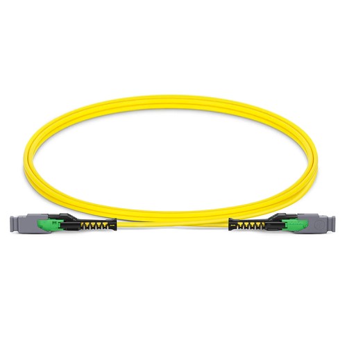
Malaysian upgrade projects can use this configuration where its interface and fiber map align with both the installed cabling and the new hardware. The 16FMMCSMF jumper links two MMC-16 APC female interfaces with sixteen OS2 fibers in a single 2.5mm plenum cable. It is created for dense single-mode patching where a compact connector footprint and controlled fiber assignment matter as much as optical loss. G.657.A1 glass supports routing through crowded managers without abandoning single-mode bend behaviour.
Product Highlights
- MMC Female to MMC Female, 16 Fibers
- OS2 9/125μm, G.657.A1
- MMC insertion loss ≤0.35dB, return loss ≥60dB
- Jumper Polarity wiring scheme
- 2.5mm Plenum (OFNP) cable
- Standard length options: 1m (3ft), 2m (7ft), 3m (10ft)
Specifications
| Part Number | 16FMMCSMF |
|---|---|
| Manufacturer | HT |
| Connector A | US Conec MMC Female (Non-Pinned) |
| Connector B | US Conec MMC Female (Non-Pinned) |
| Polish Type | APC to APC |
| Glass Fiber | G.657.A1 |
| Fiber Mode | OS2 9/125μm |
| Wavelength | 1310/1550nm |
| Fiber Count | 16 Fibers |
| Polarity | Jumper Polarity |
| Cable Outside Diameter (OD) | 2.5mm |
| Cable Jacket | Plenum (OFNP) |
| Min. Bend Radius (Optical Fiber) | 10mm |
| Min. Bend Radius (Fiber Cable) | 20/10D (Dynamic/Static) |
| Tensile Strength (Long Term) | 30N |
| Tensile Strength (Short Term) | 100N |
| Insertion Loss | ≤0.35dB |
| Return Loss | ≥60dB |
| Attenuation at 1310nm | ≤0.35dB/km |
| Attenuation at 1550nm | ≤0.21dB/km |
| Operating Temperature | -10 to 60°C (14 to 140℉) |
| Storage Temperature | -10 to 70°C (14 to 158℉) |
Where this MMC-to-MMC jumper fits
Use the finished assembly between MMC adapter positions or other non-pinned MMC connection points in a structured cabling channel. The two terminations are female, meaning that the mating interface must come with the corresponding guide pins. It is not equivalent to a universal replacement for an LC duplex cord: the sixteen fibers remain in one multi-fiber interface at every end, making this jumper assembly most valuable in parallel-optics and compact high-density panel environments.
Optical budget and routing details
Every MMC connection is specified at 0.35dB maximum insertion loss and at least 60dB return loss. Those ratings belong in the channel calculation alongside each adapter and trunk in the route. The completed cable has a 10mm minimum fiber bend radius and a 20/10D dynamic/static cable bend need; leave enough space behind the mounted panel to meet those limits rather than forcing the boot into a sharp turn.
Lengths, polarity and incoming inspection
Normal length options are 1m (3ft), 2m (7ft) and 3m (10ft), with other lengths available in feet or meters. This variant uses jumper polarity, which should be checked against the installed link rather than assumed from the mating connector shape alone. determine APC-to-APC compatibility, inspect the two ferrules and determine that the mounted panel key orientation matches the mating connector before joining the interfaces.
Ordering and Factory Support
Specify 16FMMCSMF with the appropriate length and unit count. For a non-standard route, document the desired length, labelling and packing information; our team might also inspect polarity and gender against the panel assignment plan before the product is built. For Malaysian upgrades, our team can compare the requested build with the existing environment before production begins.
Transceivers
Malaysia Fiber Optic Supplier
Malaysia Fiber OpticsFactory Address: Block 5, Wangtang Industrial Park,Nanshan Area, Shenzhen,China
Malaysia Office: 68000 Ampang,
Selangor, MYhttps://www.fiberoptic.com.my