


MTP 8F Male Type 1 Fiber Loopback Module, OS2
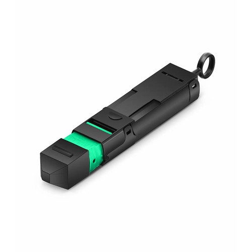
Malaysian upgrade projects can use this configuration where its interface and fiber map align with both the installed cabling and the new hardware. This fiber loopback module comes with a self-contained optical path that returns the transmit signal directly into the receive channel of the port under test: 8F, OS2, in a MTP configuration. Plugged into the interface, it lets a single technician determine transmitter output, receiver sensitivity and port assignment without a second device, a patch cord pair or a far-end loop.
Product Highlights
- Easy Insertion and Extraction with Push-pull Design
- Used in Testing 40G or 100G MPO/MTP® Interface Transceivers
- Test the Quality of Each Channel, Self-loop Test of a Single MTP Interface Optical Module with MTP Cable
- Used to Test the Transmission Capability and Reception Sensitivity of Optical Network Equipment
- US Conec MTP® Connector
Specifications
| Fiber Type | OS2 9/125μm |
|---|---|
| Fiber Connector | MTP® Male, APC |
| Insertion Loss | SM (G657.A2) ≤1.5dB |
| Return Loss | SM≥50dB |
| Insert-Pull Test | 50times, IL Change<0.5dB |
| Size | 80mm*10mm |
| Operation Temperature | -40 to 75°C (-40 to 167°F) |
| Housing Material | PC |
What loopback testing actually proves
A loopback module closes the optical circuit inside one device: the transmitter launches light, the diagnostic module returns it, and the receiver must lock onto its own signal. When the link comes up clean under those conditions, the port has proven its transmitter power, its receiver sensitivity and its internal signal integrity in one step. It is the fastest way to independent a bad port from a bad cable plant, as the completed cable plant is entirely removed from the test.
Burn-in and production-line testing
Switch and transceiver manufacturers run loopback modules through thousands of insertion cycles on the production line: each port of each unit is exercised before this version ships. The insert-pull test rating on the supplied module reflects that duty - the housing, latch and ferrule are built to survive repeated daily mating without the insertion loss drifting beyond its specification.
Testing parallel-optics transceivers
MTP-interface loopbacks serve the parallel-optics generations: 40G and 100G SR4-class ports on 8 fibers, 100G and 400G DR4-class ports on 12 and 16 fibers, and high-radix multimode interfaces on 24 fibers. The diagnostic module seats in place of this trunk assembly cable and returns each lane to its receiver, meaning that a full port test takes seconds instead of a cable plant and a far-end partner.
Male and female versions and when each is used
The gender of the loopback must agree with the port under test: transceiver interfaces with guide pins expect a female module, and pinned trunk-side interfaces expect the reverse. Using the wrong gender is not designed to merely fail to latch - it might damage the guide pins, which are not equivalent to field-replaceable. The gender is marked on the housing; validate it against the port before each insertion.
Type 1 fiber mapping and channel alignment
Inside a multi-fiber loopback, the assignment decides which transmit lane returns to which receive lane. Type 1 assignment pairs the lanes in the order the optics expect, meaning that every channel of the port under test sees its own signal returned on the intended receiver. A wrong assignment produces crossed lanes, which looks exactly like a wiring fault and wastes hours of troubleshooting - the assignment is marked on the diagnostic module so the test setup is unambiguous.
Handling, wear and service life
A loopback module is a precision test tool, and it stays one only while its latch, housing and ferrule survive daily duty. The insert-pull rating is generous, but it is not equivalent to infinite: track the mating count in the test log, and retire a module that has served a production line for years before its wear becomes the hidden cause of failing ports. A worn latch that seats loosely adds loss that masquerades as a bad receiver - the cheapest instrument in the kit might waste the most expensive hours.
A bench test workflow that scales
The productive way to use loopbacks is a fixed routine: inspect the diagnostic module ferrule, mate it with the port, bring the interface up, record the per-lane status and the receive power, then unmate and cap the diagnostic module immediately. With the routine fixed, a technician qualifies a full chassis of ports in the time an improvised setup spends on one line card. The consistency also makes the records comparable - the same module, the same procedure, the same pass criteria across each site and each batch of hardware.
Sparing and kit planning
Loopbacks belong in each commissioning kit the way a known-good patch cord does. Plan one module per interface type per crew, plus a spare that stays sealed in its bag; the cost of an extra module is trivial against a truck roll to re-test a suspect port. Label every module with its interface, fiber count and attenuation so the right one comes out of the bag on the first try, and log its insertion count so a worn test tool never becomes the hidden cause of failing ports.
Selecting the right loopback for the task
Four decisions define the diagnostic module: the mating connector interface must agree with the port under test, the fiber count must cover the lanes the optics use, the assignment type must pair the lanes the way the transceiver expects, and the attenuation must reflect the channel loss calculation the test plan calls for. Getting all four right at order time is what turns a loopback from a drawer of adapters into a dependable instrument. When the need sits outside the standard configurations, the factory might determine a made-to-order build - connector combinations, assignment variants and other attenuation ratings are all manufacturable options.
Testing and Inspection Practice
Each loopback module is optically tested before packing: insertion loss of the whole loop is verified against the specification, and the ferrule end faces are inspected for scratches and contamination. The diagnostic module ships with its dust cap fitted and the test result available on request.
Ordering and Customization Support
Refer to the supplied module by connector interface, fiber count, polish and attenuation when seeking a quotation. For other attenuation ratings, assignment types or connector combinations, send the test need with the inquiry and the factory will determine the manufacturable specification. For Malaysian upgrades, our team can compare the requested build with the existing environment before production begins.
Transceivers
Malaysia Fiber Optic Supplier
Malaysia Fiber OpticsFactory Address: Block 5, Wangtang Industrial Park,Nanshan Area, Shenzhen,China
Malaysia Office: 68000 Ampang,
Selangor, MYhttps://www.fiberoptic.com.my