


LC APC to Unterminated Fiber Pigtail, Simplex, OS2, 0.9mm
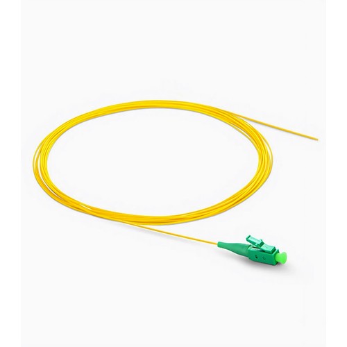
Malaysian upgrade projects can use this configuration where its interface and fiber map align with both the installed cabling and the new hardware. This fiber pigtail terminates outside-plant or backbone cable into a connectorized panel: LC APC to Unterminated Fiber Pigtail, OS2 glass, with a factory-polished LC APC connector on one end and a prepared fiber strand on the other. Fusion-spliced onto the incoming cable, it turns a raw fiber route into a documented, testable port. Malaysian upgrade teams can use this detail to compare the new assembly with the installed cabling records.
Product Highlights
- Precision Zirconia Ferrule Connectors Ensure Low Loss
- Easy-strip 900µm Tight-buffered Coating
- Color-Coded Cable Jacket for Easy Identification
- Support Both Fusion and Mechanical Splicing
- G.657.A1 Bend Insensitive Fiber & 10mm Min. Bend Radius
Specifications
| Connector A | LC APC Simplex |
|---|---|
| Connector B | Unterminated |
| Fiber Count | 1 Fiber |
| Fiber Grade | G.657.A1 |
| Fiber Mode | OS2 9/125μm |
| Wavelength | 1310/1550nm |
| Jacket Color | Yellow |
| Cable Jacket | PVC (Unrated) |
| Min. Bend Radius (Optical Fiber) | 10mm |
| Min. Bend Radius (Fiber Cable) | 10/5D (Dynamic/Static) |
| Connector Durability | 1000 Times |
| Attenuation at 1310nm | 0.36dB/km |
| Attenuation at 1550nm | 0.22dB/km |
| Insertion Loss | ≤0.3dB |
| Return Loss | ≥60dB |
| Operating Temperature | -40 to 75°C (-40 to 167℉) |
| Storage Temperature | -45 to 85°C (-49 to 185℉) |
| Connector Type | LC to Unterminated |
| Fiber Count | 1 Fiber |
| Fiber Grade | G.657.A1 |
Why pigtails remain the standard termination
A pigtail is half a connection: one end is a factory-completed connector, polished and tested under process control; the other is a bare fiber strand ready for the splice. Fusion-splicing that strand onto the deployed cable brings the mating connector quality of the factory to a field route. The result outperforms field-polished connectors on insertion loss, return loss and long-term stability, and it outperforms pre-terminated trunks when the route length is uncertain or the pathway is difficult to pre-measure.
Fusion splicing practice that protects the budget
A good splice starts long before the splicer arcs: strip the strand cleanly, cleave square, keep the sleeve staged, and protect the completed splice in the tray with the bend radius respected. The tight-buffered 0.9mm coating on this pigtail strips in one motion and seats cleanly in standard splice sleeves. Done well, a fusion splice adds less attenuation than a connector pair and stays stable for the life of the plant. Malaysian upgrade teams can use this detail to compare the new assembly with the installed cabling records.
Mechanical splicing as the field fallback
Where a fusion splicer is not equivalent to available, mechanical splices get the link up: the strand cleaves, seats in the mechanical splice body and locks against the field fiber. The loss is higher than a fusion joint and the reflectance worse, meaning that the practice is a fallback rather than a standard - but for urgent restoration work a pigtail that supports the two methods keeps the option open.
Choosing the fiber mode for the plant
Single-mode OS2 serves long links, PON access and any plant where distance or wavelength plans matter; the bend-insensitive glass grade keeps attenuation stable in dense trays. OM3 and OM4 multimode serve hardware rooms and data halls where transceiver cost favors short-reach optics. OM1 and OM2 remain in service in legacy plants and must be matched like-for-like. The pigtail mode must equal the completed cable plant mode - a mismatch splices poorly and performs worse.
Bend-insensitive glass in dense trays
Splice trays and panel rear spaces punish fiber: tight routing, crowded dressing and the occasional hurried re-entry all bend strands beyond what legacy single-mode tolerated. The bend-insensitive grade used in this pigtail holds attenuation stable at bend radii that would fog conventional glass, which keeps the link margin intact after the tenth tray opening, not just at commissioning. Malaysian upgrade teams can use this detail to compare the new assembly with the installed cabling records.
A splicing workflow that scales
Productive termination crews work to a fixed routine: mount the tray, dress the completed cable, splice the pigtails color by color, protect every joint, test every completed port, then close and label. With the routine fixed, a two-person crew terminates a full frame position in a predictable time, and the test record maps cleanly onto the documentation. The consistency also makes quality auditable - same materials, same sequence, same pass criteria across each site.
Sparing and kit planning for termination work
Pigtails belong in the termination kit in counted sets with spares: strands break, connectors get contaminated beyond recovery, and a missing spare converts a ten-minute task into a second visit. Plan one spare set per frame position, keep spare strands capped and bagged, and record which set went into which tray so replacement stock can generally be ordered to the identical specification.
Selecting the right pigtail for the job
Five decisions define the order: the mating connector family must agree with the mounted panel, the polish must agree with the plant, the fiber mode must agree with the completed cable, the construction must agree with the route, and the count must agree with the tray capacity. Getting all five right at order time is what turns a box of strands into a dependable termination. Where the need sits outside the standard configurations, the project-specific platforms cover the remaining combinations.
Testing and Inspection Practice
Each pigtail is optically tested before packing: insertion loss and return loss are verified on every terminated leg, and the ferrule end faces are inspected for scratches and contamination. The strands ship coiled, capped and bagged, with the test results available on request.
Ordering and Customization Support
Refer to this pigtail by connector, polish, fiber mode, fiber count and construction when seeking a quotation. For configurations outside the listed options - mixed connector families, jacket ratings, lengths or project packing - send the need with the inquiry and the factory will determine the manufacturable specification. For Malaysian upgrades, our team can compare the requested build with the existing environment before production begins.
Transceivers
Malaysia Fiber Optic Supplier
Malaysia Fiber OpticsFactory Address: Block 5, Wangtang Industrial Park,Nanshan Area, Shenzhen,China
Malaysia Office: 68000 Ampang,
Selangor, MYhttps://www.fiberoptic.com.my